Otto is a monkey plush that we found in a highway store during a trip with my girlfriend in February 2017.
Its ability, while being extremely cute, was to listen to you, then walk and repeat all things with a higher pitch.
My goal was to make it more powerful by transforming it into a vocal assistant.
This is the first part of a series about Otto.
Originally, it was composed by the following hardware:
A motor connected to his legs for allowing him to walk
A simple, closed (for modifications), built-in board
A microphone and a speaker
A push button to start the listening phase
Four AA batteries
A switch to completely power off the circuit
I wanted to replace all these things with fresh and programmable hardware.
The real challenge here was to find the rights components that fitted in the original enclosure. The available space wasn’t much, so every choice had to be done conscientiously.
Base board
The preferred hardware for this project are Raspberry PI boards.
They are tiny and powerful enough to allow developers to use a high-level programming language and built-in libraries without flashing the software every-time.
Furthermore, you can debug your application in a more comfortable environment.
The best hardware at the time was the Raspberry Pi Zero W. Launched at the end of February 2017, the Pi Zero W has all the functionality of the original Pi Zero but with added connectivity.
The board was not enough for such a project, so I added additional hardware.
Audio components
To build a vocal assistant, we need audio components. The requirements for these components are, of course, a speaker and a microphone.
For the microphone, I tried a USB microphone. The problem with this accessory was that it was not as sensible as I wished. Furthermore, an additional USB hub was required to connect it.
Moreover, I couldn’t connect a raw speaker easily.
For this reason, I opted to buy an additional board that accomplished this task very well: ReSpeaker 2-Mics Pi HAT.
ReSpeaker 2-Mics Pi HAT is a dual-microphone expansion board for Raspberry Pi designed for AI and voice applications.
The board is developed based on WM8960, a low power stereo codec. There are 2 microphones on both sides of the board for collecting sounds. It also provides 3 APA102 RGB LEDs, 1 User Button, and 2 on-board Grove interfaces.
I did not plan to connect LEDs to my board, but the fact that this HAT has built-in LEDs made me think to use them.
 ReSpeaker 2-Mics Pi HAT — Hardware specifications
Then I took an old Bluetooth mini-speaker, disassembled it, and connected it to the JST 2.0 Speaker Out port.
To make it work, you have to install their drivers on your board. Drivers are also used to control LEDs within your application via a standard protocol.
Hint: when you install a shield, all your GPIO pins are covered. It’s useful to know which pins are **really used* by your board. To accomplish that, use https://pinout.xyz/*
For example, for this board, check out this link: https://pinout.xyz/pinout/respeaker_2_mics_phat
Powering the board
The Raspberry Pi board can be easily powered via USB 5V input. The problem with this approach is that you have to buy a battery pack and connect it via USB.
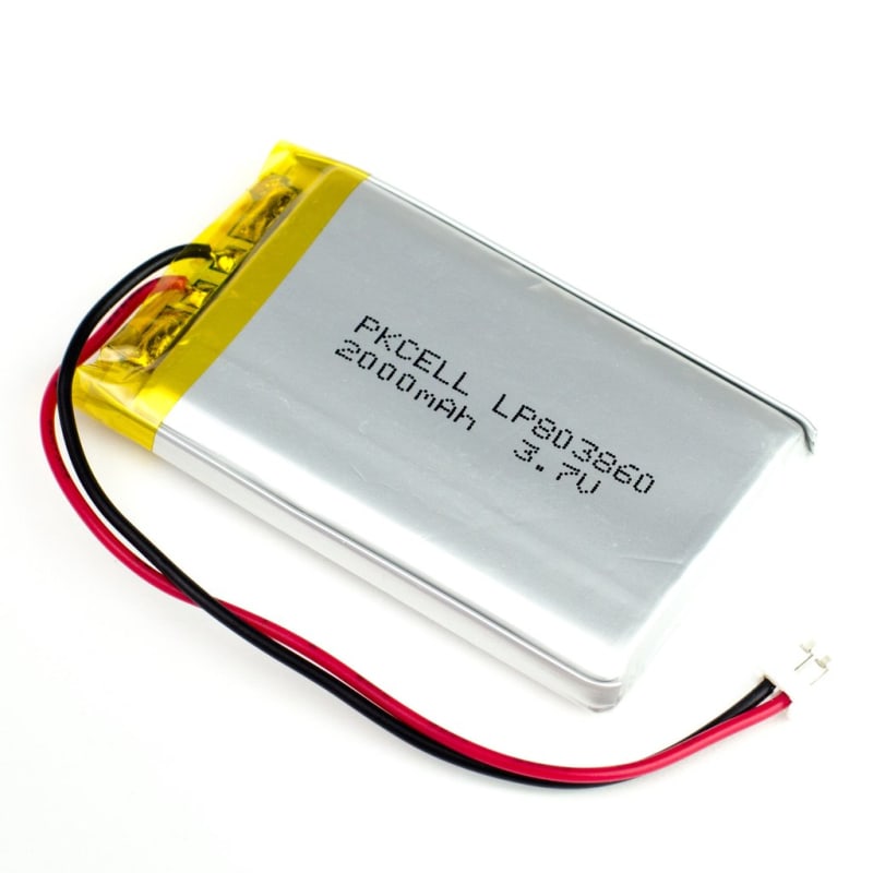
I didn’t find any battery pack small enough to fit my plush, then my unique alternative was using LiPo batteries.
You can’t connect your LiPo battery to your board, you have to use a converter. It can be powered by any 3.7V LiIon/LiPoly battery, and then it converts the battery output to 5.2V DC.
Initially, I bought a LiPo SHIM, but I didn’t notice that this controller provides power to your board without charging your batteries.
For this reason, I switched to Adafruit PowerBoost 500 Charger.** It has a built-in battery charger circuit. You’ll be able to keep your project running even while charging the battery!
 Adafruit PowerBoost 500 Charger
Additional hardware
The software uses the “hot-word” concept to start the interaction. Basically, it continuously listens for a hot-word, like “Hey Otto”, then you just talk and say commands.
For having an alternative method to start the interaction, I installed a** push-button **connected directly to the GPIO board, at the GPIO8 pin.
Now only one thing was missing: the power on-off switch.
I connected this simple component to the PowerBoost Charger via its ENABLE port. The purpose of the ENABLE port is to disconnect the output completely.
Connect everything together
Here you can see in details the complete circuit diagram (https://www.circuit-diagram.org/circuits/0d85ce05)
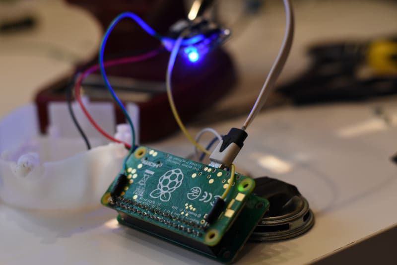
And here a snapshot of the work:


Top comments (0)